Unlock Your Washer’s Secrets: Decoding the Ge Washer Parts Diagram
Unlock Your Washer’s Secrets: Decoding the Ge Washer Parts Diagram
Behind every smooth, efficient laundry cycle lies a precision-engineered machine working in silence—often out of sight, but never out of necessity. The Ge Washer Parts Diagram is the master key to understanding how each component transforms fabric, water, and detergent into clean, fresh clothes. Whether you’re a technician diagnosing breakdowns, a homeowner troubleshooting performance, or a DIY enthusiast expanding repair knowledge, mastering this diagram reveals everything from routine maintenance to complex repair logic.
This essential guide breaks down the critical washer components and their interrelationships, illustrated through a detailed parts diagram, to empower informed action and long-term reliability. The Ge washer system, built on decades of engineering refinement, relies on a coordinated network of mechanical, hydraulic, and electrical parts working in tandem. At its core, the machine transforms kinetic energy and water pressure into mechanical agitation and rinsing motion.
But without understanding the precise function and placement of each component—visualized clearly in a Ge washer parts diagram—even confident users risk misdiagnosis, inefficient repairs, or unintended damage. The diagram serves as both a diagnostic tool and a maintenance roadmap, offering clarity on how incoming water interacts with internal mechanisms, detergent dispensers, and load-support structures.
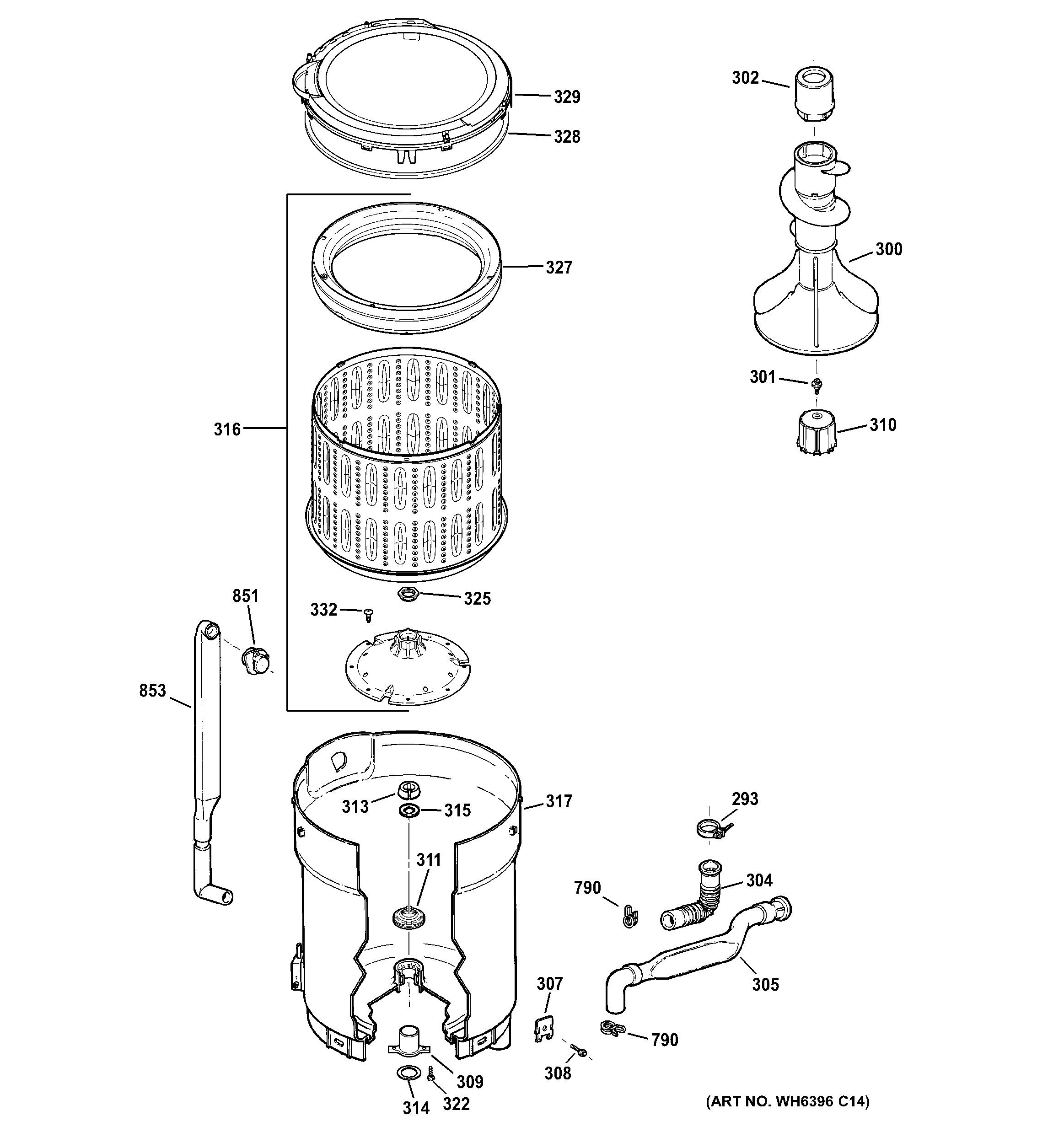
Central to the washer’s operation are the drum and drum motor assembly, the pulsator, detergent dispenser, agitator or impeller, and the modular basket system.
The drum—the round, rotating cylinder—serves as the primary chamber where laundry tumbles. Historically, models used an agitator; modern Ge washers rely on brushless impellers or rotary drums with oscillating motion, reducing wear and improving cleaning efficiency. These components are clearly labeled in any detailed parts diagram, often denoted by part numbers and placement schematics that match factory blueprints.
The drum motor, typically embedded at the center or periphery, drives rotational or oscillatory movement, synchronized with tolling water intake via the pulsator. Beneath the drum, the detergent dispenser plays a pivotal role in chemical delivery. Mounted along the drum wall, it releases detergent precisely when water flow activates it—ensuring optimal dissolution without early saturation.
“Timing and distribution are everything—poor dispensing leads to inefficient wash results or residue buildup,” notes industrial appliance technician James Carver. The diagram highlights precise coordination between the dispenser motor, control solenoid, and load sensors, enabling automated dosage based on cycle selection and load detection. Nestled within the drum’s upper section lies the pulsator, a small but vital component.
This piston-like post operates in tandem with the drum to generate gentle to vigorous tumbling forces, depending on cycle type. In high-efficiency models, the pulsator works with advanced brushless impellers to reduce water and energy use while maintaining cleaning performance. Diagrammatically, the pulsator’s position—often near the drum’s top—illustrates its direct influence on load movement dynamics and wear patterns over time.
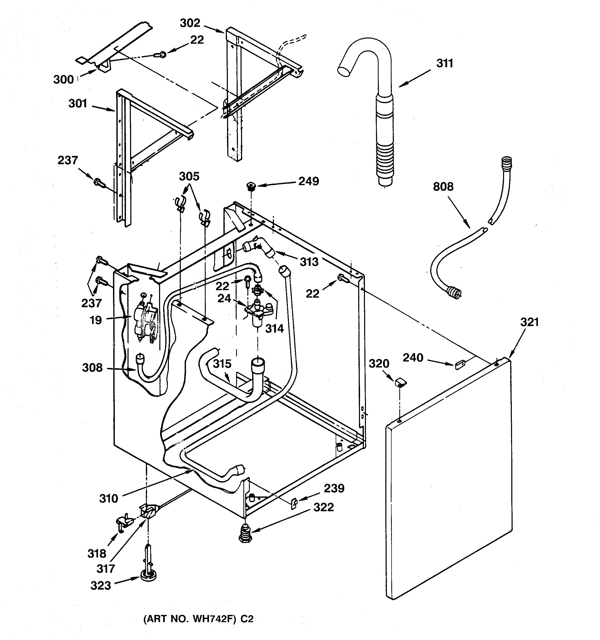
The washer’s water introduction system is orchestrated by a network of valves, hoses, and the pump assembly. The water inlet valve regulates flow timing relative to drum rotation, ensuring proper saturation for cleaning. The pump, typically located beneath the front panel or at the drum’s bottom, circulates water under controlled pressure.
“Misaligned water valves or a failing pump are common causes of inconsistent wetting,” explains mechanical engineer Sarah Lin, “visually tracked via pressure gauges and diagram cross-referencing.” These components are systematically outlined in the Ge diagram, enabling targeted inspection and replacement. Another cornerstone of proper operation is the load balancing features embedded in the washer’s assembly. The basket system, often split into two or four chambers, stabilizes textiles during rotation, minimizing excessive movement that can cause fabrics to snag or garments be damaged.
Modern iterations use high-impact plastic baskets with reinforced ribs—mapped clearly in the parts diagram as modular components designed for snug fit and long durability. Even automatic balancing sensors rely on physical linkages explained through detailed schematics, ensuring optimal load distribution for efficient cleaning and reduced wear. Beyond mechanical components, electrical and control systems are increasingly integrated into Ge washer design, with circuits controlling motor speed, door locking, sensor feedback, and cycle selection.
While invisible in the physical diagram, these elements interact seamlessly with hardware parts—drone-like communication across components governed by programmable logic. The overarching diagram often includes electrical flow paths and sensor placement markers, offering a full-system visualization essential for troubleshooting modern electronic washes. To maximize reliability, users should consult the Ge washer parts diagram not as a static chart, but as a dynamic roadmap.
Routine maintenance—checking seals, cleaning pulsators, testing dispenser flow—becomes systematic when each part’s function and location are memorized through visual guidance. Repairs that once required guesswork now follow precise, diagram-backed protocols, reducing downtime and part waste. Many home users have reported extending their washer’s lifespan by years by referring to these diagrams during do-it-yourself interventions.
Clearly, the Ge Washer Parts Diagram is far more than a visual aid—it is the foundation of informed, confident appliance care. From understanding how water pulses through the drum to pinpointing faulty motors or worn valves, every component’s role is made legible. In an era where appliance longevity and energy efficiency matter more than ever, mastering this diagram empowers users to be proactive, knowledgeable stewards of their washing machines.
Key Components in Action: How the Ge Washer Delivers Clean, Consistent Results
The Ge washer operates through a sequence of precisely timed mechanical and electronic interactions—each governed by its labeled component in the parts diagram. At the start of every cycle, the user initiates a selected wash mode, sending signals to the control module. The water pump activates, drawing fluid from the hot water inlet—regulated by precision valves—into the drum’s lower region. As the pulse begins, the pulsator oscillates, generating gentle rocking motion or vigorous tumbling, depending on the cycle’s intensity.This movement, clearly shown in the diagram, lifts and drops fabrics without excessive abrasion. Simultaneously, the detergent dispenser triggers via a solenoid, releasing a measured dose synchronized with water flow. If the dispenser becomes clogged or misaligned—conditions easily identified through visual diagram mapping—cleaning results suffer, leading to residue or fabric damage.
Integrated sensors monitor load weight, moisture levels, and temperature, delivering real-time feedback to maintain optimal chemistry and cycle timing. The drum’s motion continues, aided by rubber dashpads that cushion fabric contact. Modern Ge models use brushless impellers or low-profile rotating plates, details accurately reflected in the parts diagram, minimizing friction while maximizing cleaning action.
As the cycle progresses, excess water enters via intelligent valve control, ensuring fabrics absorb only what’s needed—critical for reducing drying time and energy use. By the cycle’s end, the vanish cycle or spin function activates, rapidly rotating the drum to extract moisture. Timing and pressure are fine-tuned by the motor and drum assembly—both visually tracked through diagnostic methods referenced in the original diagram.
When appreciated, this sequence transforms raw power into fresh, vibrant laundry with minimal effort.
Every wire, gear, and valve serves a purpose within this choreographed system, and the Ge washer parts diagram decodes that choreography step by step. Whether diagnosing an odd noise, replacing a faulty drive belt, or upgrading components for energy efficiency, referencing this diagram transforms ambiguity into actionable insight.
Fixing a leaking water valve becomes a matter of locating the flex hose connection and valve housing—components clearly marked and explained. Loose drain hoses sagging over time? The diagram pinpoints their mounting brackets and alignment points.
Even subtle wear, such as cracked seals or corrosion around motor mounts, reveals itself through detailed visual scrutiny guided by diagram annotations. Skilled users and service technicians alike recognize that mastery of this diagram isn’t merely about assembly—it’s about cultivating a deep understanding of mechanical relationships. With each repaired component or optimized wash, the washer evolves from a basic appliance into a reliable, long-lasting utility.
Mapping the Diagram for Precision: Tools and Techniques
Interpreting the Ge washer parts diagram effectively requires more than visual inspection—it demands technique. Users should begin by identifying the control panel at the front, often housing cycle buttons and error code indicators. Next, locate the front access panel, typically on the left or top, which grants entry to internal components while preserving watertight integrity.Labeled diagrams often use color coding or icons: red for high-power motors, blue for water valves, yellow for sensors. Pay close attention to mounting points—the bolt patterns, clip tabs, and alignment pins guide safe disassembly. The drum assembly, often centered with a hub-and-lock system, must be handled with care to preserve bearing integrity.
Photography and digital overlays—developed from the original blueprint—assist frontline technicians and DIYers alike. Cross-referencing with labeled schematics helps isolate issues: for example, a cracked impeller y-axis or a stripped solenoid coil becomes immediately recognizable when mapped against expected motion and stress zones. Using the diagram as a living guide, users can trace failure patterns.
Frequent spin cycle failures might trace to worn bearings or misaligned drive gears—conditions easy to spot when paired with visual clues from the imported parts diagram. Similarly, persistent water leaks often stem from O-rings or valves labeled with part numbers, enabling rapid, accurate replacement. In conclusion, the Ge Washer Parts Diagram is not just a technical illustration—it’s the backbone of informed maintenance, precise repairs, and sustained performance.
By decoding its symbols and layout, users unlock a world of efficiency, longevity, and reliability hidden beneath layers of fabric and machinery. Mastering this diagram transforms laundry day from a routine chore into a testament of knowledge and control—one spin at a time.

Related Post

Chase Visa Card Login Access: Your Ultimate Shortcut to Seamless Card Management

Christy Capel: Architect of Environmental Resilience and Sustainable Innovation

Is P Diddy Hitched? Unraveling the Marriage Mystery Behind the Legendary Music Mogul

From Polecats to Presidents: How American Dad’s Voice Cast Became Cultural Icons


